
Let’s take another look at that tail...better
pull up a chair too.
Rudder
Trim 101 is brought to you by Terry Cooper & Ed Durand. Thanks to Terry’s
lesson and an Article from Ed on the very tragic Reno 2011 Air Race
crash of “Galloping Ghost” (The cause of the crash was a defective/broken off
Elevator trim tab on a modified P-51D). I can now follow through on my promise
to explain the significance of the trim tab. I am also most grateful for
Terry’s conversation; a quick lesson on rudder trim
digressed into a lesson on fixed pitch and constant speed propellers, which
further digressed into a lesson on the propeller governor, but not before a
digression on private aircraft powerplants (such as the Lycoming and
Continental), before finally digressing back to trim tabs! A very well spent and much appreciated
hour and a half, Thanks Terry and Ed!

That's a nice Hurricane tail

Rudder Trim:
Pictured above you can see the rudder and
tail of our Hurricane (and an additional picture that’s easier to see the
rudder trim). The solid, green vertical bar in the foreground of the picture is
the Hurricane’s rudder trim tab. The trim tabs are primarily used to relieve
pressure from the control columns. For instance, when air is flowing over the
wings and stabilizers it puts pressure on the control surfaces depending on the
direction you are heading. Some aircraft have trim tabs on their ailerons,
elevators, and rudders. I believe our Hurricane only has Rudder and Elevator
trims. However the rudder trim tab also serves an additional purpose.
The propeller is essentially a gigantic
gyroscope. It, when spinning, pretty much forms a giant disk. It is also
spinning in a particular direction. On aircraft that are tail draggers, that
is, aircraft that have their landing gear beneath the tail section and rests on
its tail, the rudder trim is critical for take-off. The Hurricane is a tail
dragger. So when the Hurricane is moving forward on takeoff, it wants to go in
the direction of the spinning propeller. That’s because there is force acting
on the aircraft, 90 degrees, causing it to want to do a 180, or change
directions. So if the propeller is spinning clockwise (from the pilot’s point-of-view),
on take off, force will be hitting the aircraft on the pilot’s right-hand side
making it want to spin-out or turn 180 degrees. By activating rudder and
setting the rudder trim, the pilot is able to counter-act that 90 degree force
and maintain a particular heading for take off. Likewise while the plane is in
flight that force is still pressing on the aircraft but to a lesser extent
because the power level is lower during cruise than it is during take-off.
However, the principle remains the same, the rudder can be utilized or the trim
to counter act the force and help the pilot maintain a straight heading.
Now, that’s about it for the Rudder trim
and I apologize if I horribly botched that explanation. If I need to make
anything clearer or if you have any questions I will try to answer them next
week! Unfortunately I didn’t snap a picture of the reinstalled locking pin and
landing gear on the Spitfire, however, it looks exactly the same as the
installed landing gear from last weeks blog with the addition of a tire. All
you need to do is imagine a stainless steel pin instead of a brass one!
Ok so now let’s talk about what happened
Saturday. Well again I was not working on the Hurricane, but equally exciting
things were done on the Spitfire. Philip and I were tasked with running a
compression check on the big V-12 Merlin, the heart of the Spitfire (and
eventually on our Hurricane {but the smaller Merlin 29}). I started this blog
in the hopes of keeping it about the Hurricane but I seem to have gone off-topic
the past few weeks. That doesn’t mean that nothing has been done on the Hurricane,
we have a small army of volunteers working on it. I will make sure that if I do
not work on the Hurricane a particular Saturday, I will take note and pictures
of what’s being done. Then we can return to the original purpose of this blog.
In the mean time, I hope you have found the work being done on the Spitfire
interesting, I sure do. And who knows, the Hurricane will need a compression
check done eventually so consider this a practice round!
The Compression Check:
The compression check is done to ensure
that the cylinders are maintaining the proper level of compression during the
compression stroke of a reciprocating engine. Piston engines in aircraft are
generally 4 stroke, 5 cycle/event engines:
1)
Intake stroke, where the piston moves downwards in the cylinder drawing
in fuel and air mixture.
2) Compression stroke, where the
piston moves back up in the cylinder compressing the fuel/air mixture.
* Then you have ignition or combustion,
where the spark plug ignites the fuel/air mixture once the piston has
compressed it and reached a certain point before
top-dead-center (the point when the piston is at its highest on the upstroke
before going back down).
3) Power stroke, where the ignited
fuel/air mix drives back down the piston doing useful work, turning the crankshaft.
4) Exhaust stroke, where the spent
fuel/air mix is pushed out the exhaust valve as the piston goes back up.
Then the process repeats; 4 distinct strokes, 5 different events. The only time the piston does any useful work is on the power stroke because that is the stroke where it is being used to turn the crankshaft. In order to have a successful power stroke, the fuel/air mixed needs to be compressed to a certain psi (pounds per square inch) of pressure before it is ignited. If not, it will not exert the appropriate amount of force during the power stroke and the engine will run inefficiently (also probably a sub-par explanation but I haven’t got that far in my Powerplant text yet).
The first thing we had to do on the
Spitfire was remove the spark plug leads and spark plugs. The Spitfire has 24
sparkplugs all together, two per cylinder. By removing one bank on each side,
an adapter could be placed in and the cylinder compressed (more about that
later though).
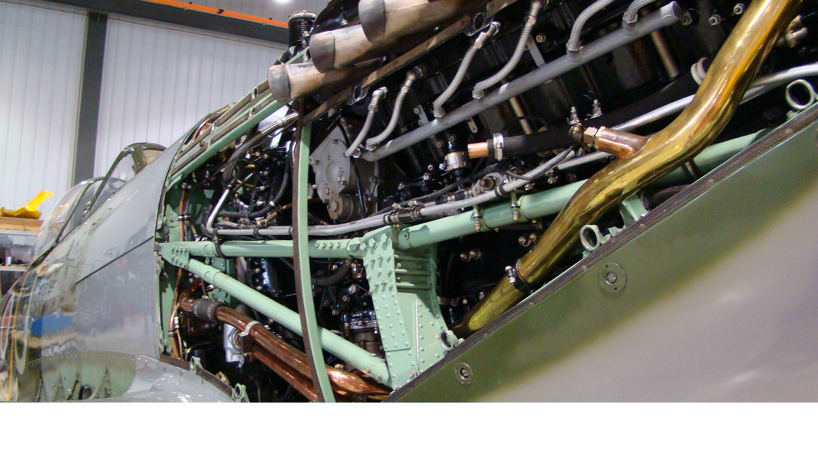

Packard built Merlin 266
Pictured above you can see the beautiful
Packard built Merlin 266 in the Spitfire. The silver wires are the Spark Plug leads.
They screw into the top of the spark plug and send the electrical current, or
spark, to the spark plug from the Magneto. That spark then ignites the fuel
mixture and so on in that particular cylinder.

Above you can see two spark plugs with their spark leads removed

In the picture above you can see 5 spark plugs removed on the “A” bank. Rather than calling
the two banks of the engine left and right, the British opted for A and B. I
guess that makes more sense because depending which side you side of the engine
you look at, the “right” and “left” bank could easily be confused. We also had
to take the spark plugs out in a particular order. We took them out from the
one closest to the propeller (“A1”) to the one closest to the cockpit (“A6”).
This was to ensure that they are returned to the proper cylinder. As you can
see they are quite dirty and in need of cleaning. The engine was like running
rich (meaning a high percentage of fuel in the fuel/air mix) because most of
the flights were short. That means the Spit spent a lot of time taxiing and
running on the ground where the fuel mix is set to full rich (I believe).

Looks kind of like the space control unit I built at home
Anyways once they were out on both sides we
could do the compression test. I mentioned earlier that only 12 of the 24 were
taken out. This is because if we had removed both, when air was forced into the
cylinder it would have escaped out the other spark plug hole and it would be
impossible to do the compression test.
To do the compression test, an adapter was
fitted to the open spark plug hole and a regulator and air hose connected to
that adapter. However, before doing that, the piston in the cylinder being
tested had to be at top-dead-center (tdc).
Once the piston was in the correct position air could be forced into the
cylinder. The easiest way to tell when the piston was at tdc was by looking at the valves and camshaft.

The “B” bank camshaft and valve assembly is
to the right of the exhaust port in the above picture (look down from the 3
gears in the foreground. From there to the propeller are all 24 valves for “B”
bank). Each cylinder has two intake valves and two exhaust valves for a total
of 48 valves. To get the piston for ‘B1’ at tdc,
the propeller had to be rotated around until the nubs on the camshaft were
facing up. This means that all four valves for that cylinder would be shut. If
they were shut, the piston was at tdc
and air could be forced in through the air hose. The valves are springloaded.
When the nubs are up, there is no pressure on the spring and the valve remains
closed. When the nubs are down, pressure is put on the valve and spring and the
valve is pushed open.
However, even before that Paul put the fear
of God into me (for good reason). Because the piston is being compressed in the
cylinder, it’s being driven downwards by the air. When the piston is driven
down it wants to turn the crankshaft. When the crankshaft turns, the propeller
turns. To test the compression of the cylinder, we had to put 80 psi into the cylinder. So, essentially
80 pounds of force pushing down on that cylinder. That meant a brave soul had
to hold the propeller in place. Paul and Philip gave did an example of the test
on the first cylinder. Paul let the air in and Philip held the propeller. All
went well. However, once 80 psi was
put into the cylinder, we needed to see if it maintained that psi. The first cylinder ended up holding
64 psi. That means there was a leak
somewhere down the line and it will need to be inspected later on. In order to
pass the compression test, the cylinder cannot lose more than twenty-five
percent of its compression, so ‘B1’ just passed. The rest were all passes, the
majority loosing some compression out the exhaust ports.
Back to Paul putting the fear of God into
me. With the 80 psi being forced into
the cylinder, if that propeller was to let go or no one was there holding it,
it would spin. Quite fast. So fast, that people have been seriously injured by it. By serious, I mean a nasty gash on the
noggin, concussion, stitches, comas…(that’s
the fear of God bit) bad news. You don’t want a smack from that prop that’s for
sure.
So Paul’s holding the propeller, I plug in
the air hose (my first time too), haven’t even turned it on (which we did
slowly to gradually build the psi to
80) and I hear Paul, WOAH, WOAH, JEEZ, HEY, WOAH!?!?…I’m like OH S*@&!
What??…Immediately begin turning the dial to relieve the pressure I haven’t
even put in yet and shut the valve off thinking the gauge maybe malfunctioned? Then,
perhaps having mercy on my state of horror and for his cruel joke, Paul told me
all was ok, he was joking/testing, and good job for shutting the air off (but
next time just disconnect the hose, it’s faster). So after a mild heart attack
and a little laugh afterwards there were 10 more cylinders to check. Fortunately
there weren’t 10 more heart attacks. Once the check was done, it was on to
cleaning, replacing, and reconnecting the leads. Hat’s off to a job well done,
if I don’t say so myself.
Now, apparently I forgot to include a picture
of myself when I introduced myself 4 blogs prior. So to solve the mystery of
the masked blogger, here he is (photo courtesy of Philip). That’s yours truly
making the ladder look good/getting ready to test a cylinder on ‘A’ bank; now a
seasoned veteran in the Compression test.

Smile for the camera Chris
Ask An AM-E?
As if I haven’t
gone on long enough today, I want to include a small piece on an addition that
I want to add to future blogs. This new section will be entitled “Ask
An AM-E.” In this, I will take one reader submitted question and
ask Paul Tremblay, the AM-E, your question. We will then try to figure out an
appropriate answer. If your question is chosen, the answer to your question
will appear in the following weeks blog at the tail end! Exciting stuff. Now, keep
in mind, if a question is asked about the engine on an Air Bus A-380, you might
not get an answer (or you’ll get a googled one). BUT if you ask anything about
the Hurricane that interests you, the restoration process, being an AM-E, or
working on the myriad of other Vintage Wings aircraft, I’m sure you’ll get a
most excellent answer.
Questions can be
emailed to me at “ceaton@vintagewings.ca”. I will only be able to answer one
per week but if your question is not answered immediately, it could be answered in subsequent weeks!
You may send me the same question as a reminder if it is not answered in a few
weeks (who knows, I may be able to answer your question via email exchange!).
Well thanks for
sticking it out to the end this week, I hope it has been an enlightening,
exciting, and enjoyable read.
Until next time,
take care!
Chris
Thanks for explaining the strokes for checking compression. When do you usually replace aircraft spark plugs?
ReplyDelete-Aircraft Testing Equipment @ AvionTEq
RE:Max Williams;
ReplyDeleteRCAF V-1650-7 P51D every 15 flight hours or
mag drop if occurred first.
Peace time service...about the last of the Mustangs.